 |
|
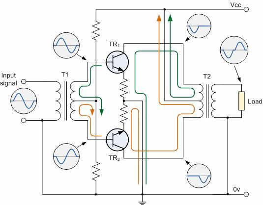
Class B Amplifiers To improve the full power efficiency of the previous Class A type amplifier it is possible to design the amplifier circuit with two transistors in its output stage producing a "push-pull" type amplifier configuration. Push-pull operation uses two "complementary" transistors, one an NPN-type and the other a PNP-type with both power transistors receiving the same input signal together that is equal in magnitude, but in opposite phase to each other. This results in one transistor only amplifying one half or 180 degrees of the input waveform while the other transistor amplifies the other half or remaining 180 degrees of the waveform with the resulting "two-halves" being put back together at the output terminal. This pushing and pulling of the alternating half cycles by the transistors gives this type of circuit its name but they are more commonly known as Class B Amplifiers as shown below. Class B Push-pull Transformer Amplifier Circuit
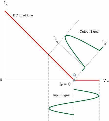
The circuit above shows a standard push-pull amplifier circuit that uses a balanced centre-tapped input transformer, which splits the incoming waveform signal into two equal cycles that are 1800 out of phase with each other and another centre-tapped transformer on the output to recombined the signals and provide the increased power to the load. The transistors used for this type of transformer push-pull amplifier circuit are both NPN transistors with their emitter terminals connected together. Here, the load current is shared between the two power transistor devices as it decreases in one device and increases in the other throughout the signal cycle reducing the output voltage and current to zero. The result is that both halves of the output waveform now swings from zero to twice the quiescent current thereby reducing dissipation. This has the effect of almost doubling the efficiency of the amplifier to around 70%. Assuming that no input signal is present, then each transistor carries the normal quiescent collector current, the value of which is determined by the base bias which is at the cut-off point. If the transformer is accurately centre tapped, then the two collector currents will flow in opposite directions (ideal condition) and there will be no magnetization of the transformer core, thus minimizing the possibility of distortion. When a signal is present across the secondary of the driver transformer T1, the transistor base inputs are in "anti-phase" to each other as shown, thus if TR1 base goes positive driving the transistor into heavy conduction, its collector current will increase but at the same time the base current of TR2 will go negative further into cut-off and the collector current of this transistor decreases by an equal amount and vice versa. Hence negative halves are amplified by one transistor and positive halves by the other transistor giving this push-pull effect. Unlike the DC condition, these AC currents are ADDITIVE resulting in the two output half-cycles being combined to reform the sine-wave in the output transformers primary winding which then appears across the load. Class B Amplifier operation has zero DC bias as the transistors are biased at the cut-off, so each transistor only conducts when the input signal is greater than the base-emitter voltage. Therefore, at zero input there is zero output. This then means that the actual Q-point of a Class B amplifier is on the Vce part of the load line as shown below. Class B Output Characteristics Curves
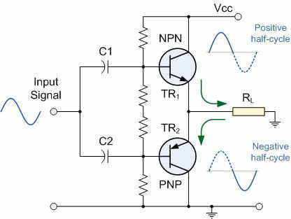
Class B Amplifiers have the advantage over their Class A amplifier cousins in that no current flows through the transistors when they are in their quiescent state (ie, with no input signal), therefore no power is dissipated in the output transistors or transformer when there is no signal present unlike Class A amplifier stages that require significant base bias thereby dissipating lots of heat - even with no input signal. So the overall conversion efficiency ( ? ) of the amplifier is greater than that of the equivalent Class A with efficiencies reaching as high as 75% possible resulting in nearly all modern types of push-pull amplifiers operated in this Class B mode. Transformerless Class B Push-Pull Amplifier One of the main disadvantages of the Class B amplifier circuit above is that it uses balanced centre-tapped transformers in its design, making it expensive to construct. However, there is another type of Class B push-pull amplifier called a Complementary-Symmetry Class B Amplifier that does not use transformers in its design therefore, it is transformerless using instead complementary pairs of transistors. As transformers are not needed this makes the amplifier circuit much smaller for the same amount of output, also there are no stray magnetic effects or transformer distortion to effect the quality of the output signal. An example of a "transformerless" circuit is given below. Class B Transformerless Output Stage
While Class B amplifiers have a much higher gain than the Class A types, one of the main disadvantages of class B type push-pull amplifiers is that they suffer from an effect known commonly as Crossover Distortion. This occurs during the transition when the transistors are switching over from one to the other as each transistor does not stop or start conducting exactly at the zero crossover point even if they are specially matched pairs. This is because the output transistors require a base-emitter voltage greater than 0.7v for the bipolar transistor to start conducting which results in both transistors being "OFF" at the same time. One way to eliminate this crossover distortion effect would be to bias both the transistors at a point slightly above their cut-off point. This then would give us what is commonly called an Class AB Amplifier circuit. |
|
|
|
Contact email: qooljaq@qooljaq.com |