 |
|
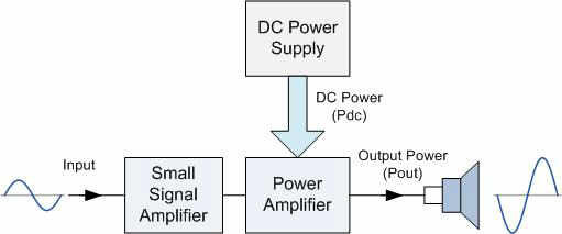
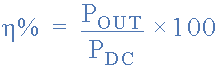
Class A Amplifier Common emitter voltage amplifiers are the most commonly used type of amplifier as they have a large voltage gain. They are designed to produce a large output voltage swing from a relatively small input signal voltage of only a few millivolt's and are used mainly as "Small Signal Amplifiers" as we saw in the previous tutorials. However, sometimes an amplifier is required to drive large resistive loads such as a loudspeaker and for these types of applications where high switching currents are needed Power Amplifiers are required. The main function of the Power amplifier, which are also known as a "Large Signal Amplifier" is to deliver power, which is the product of voltage and current to the load. Basically a power amplifier is also a voltage amplifier the difference being that the load resistance connected to the output is relatively low, for example a loudspeaker of 4 or 8Os resulting in high currents flowing through the Collector of the transistor. Because of these high load currents the output transistor(s) used for power amplifier output stages need to have higher voltage and power ratings than the general ones used for small signal stages. Since we are interested in delivering maximum AC power to the load, while consuming the minimum DC power possible from the supply we are mostly concerned with the "Conversion Efficiency" of the amplifier. However, one of the main disadvantage of power amplifiers and especially Class A type amplifiers is that their overall conversion efficiency is very low. Percentage efficiency in amplifiers is defined as the r.m.s. output power dissipated in the load divided by the total DC power taken from the supply source as shown below. Power Amplifier Efficiency
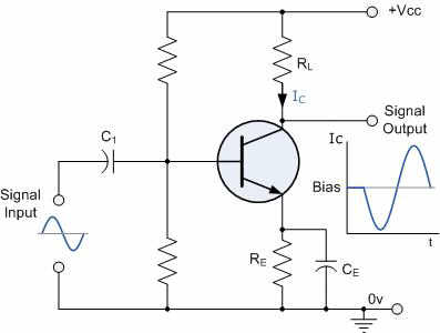
Where: N% - is the efficiency of the amplifier. For a power amplifier it is very important that the amplifiers power supply is well designed to provide the maximum available continuous power to the output signal. The most commonly used type of power amplifier configuration is the Class A Amplifier. Class A amplifier stages use the transistor in the standard Common Emitter circuit configuration as seen previously, in which the transistor is always biased "ON" so that it conducts during one complete cycle of the input signal waveform producing minimum distortion to the output. This means then that the Class A Amplifier configuration is the ideal operating mode, because there can be no crossover or switch-off distortion to the output waveform. Class A power amplifier output stages may use a single transistor or pairs of transistors connected together to share the high load current. Consider the Class A amplifier circuit below. Single-ended Amplifier Circuit
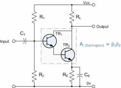
stage with the resistive load connected directly to the Collector terminal. When the transistor switches "ON" it sinks the output current through the Collector resulting in an inevitable voltage drop across the Emitter resistance thereby limiting the negative output capability. The efficiency of this type of circuit is very low (possibly 20%) and delivers small power outputs for a large drain on the DC power supply. A Class A amplifier stage passes the same load current even when no input signal is applied so large heatsinks are needed for the output transistors. However, another simple way to increase the current handling capacity of the circuit while at the same time obtain a greater power gain is to replace the single output transistor with a Darlington Transistor. These types of devices are basically two transistors within a single package, one small "pilot" transistor and another larger "switching" transistor. The big advantage of these devices are that the input impedance is suitably large while the output impedance is relatively low, thereby reducing the power loss and therefore the heat within the switching device. Darlington Transistor Configurations
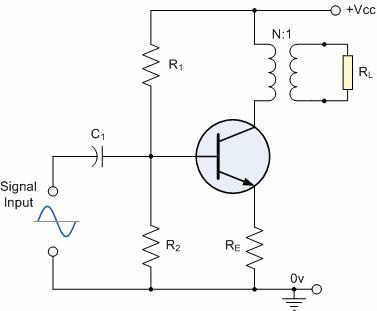
The overall current gain Beta (ß) or Hfe value of a Darlington device is the product of the two individual gains of the transistors multiplied together and very high ß values along with high Collector currents are possible compared to a single transistor circuit. To improve the full power efficiency of the Class A amplifier it is possible to design the circuit with a transformer connected directly in the Collector circuit to form a circuit called a Transformer Coupled Amplifier. This improves the efficiency of the amplifier by matching the impedance of the load with that of the amplifiers output using the turns ratio (N) of the transformer and an example is given below. Transformer-coupled Amplifier Circuit
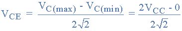
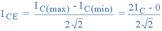
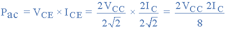
As the Collector current, Ic is reduced to below the quiescent Q-point set up by the Base bias voltage, due to variations in the Base current, the magnetic flux in the transformer core collapses causing an induced emf in the transformer primary windings. This causes an instantaneous Collector voltage to rise to a value of twice the supply voltage 2Vcc giving a maximum Collector current of twice Ic when the Collector voltage is at its minimum. Then the efficiency of this type of Class A amplifier configuration can be calculated as follows. The r.m.s. Collector voltage is given as:
The r.m.s. Collector current is given as:
The r.m.s. Power delivered to the load (Pac) is therefore given as:
The average power drawn from the supply (Pdc) is given by:
and therefore the efficiency of a Transformer-coupled Class A amplifier is given as:
This improves the efficiency of the amplifier by matching the impedance of the load with that of the amplifier using the turns ratio of the transformer and efficiencies reaching 40% are possible with most commercially available Class-A type power amplifiers of this type of configuration, but the use of inductive components is best avoided. Also one big disadvantage of this type of circuit is the additional cost and size of the audio transformer required. It is possible to obtain greater power output and efficiency than that of a Class A amplifier by using two transistors in the output stage in a "push-pull" configuration. This type of configuration is called a Class B Amplifier. |

|
|
|
Contact email: qooljaq@qooljaq.com |