 |
|
Amplifier Distortion From the previous tutorials we learnt that for a signal amplifier to work correctly it requires some form of DC Bias on its Base or Gate terminal so that it amplifies the input signal over its entire cycle with the bias Q-point set as near to the middle of the load line as possible. This then gave us a Class "A" type amplification with the most common configuration being Common Emitter for Bipolar transistors and Common Source for unipolar transistors. We also saw that the Power, Voltage or Current Gain, (amplification) provided by the amplifier is the ratio of the peak input value to its peak output value. However, if we incorrectly design our amplifier circuit and set the biasing Q-point at the wrong position on the load line or apply too large an input signal, the resultant output signal may not be an exact reproduction of the original input signal waveform. Consider the common emitter amplifier circuit below. Common Emitter Amplifier
Distortion of the signal waveform may take place because:
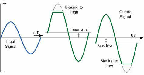
This means then that during the amplification process of the signal waveform, some form of Amplifier Distortion has occurred. Amplitude Distortion Amplifiers are basically designed to amplify small voltage input signals into much larger output signals and this means that the output signal is constantly changing by some factor or value times the input signal at all input frequencies. We saw previously that this multiplication factor is called the Beta, ß value of the transistor. Common Emitter or even common Source type circuits work fine for small AC input signals but suffer from one major disadvantage, the bias Q-point of a bipolar amplifier depends on the same Beta value which may vary from transistors of the same type, ie. the Q-point for one transistor is not necessarily the same as the Q-point for another transistor of the same type due to the inherent manufacturing tolerances. If this occurs the amplifier may not be linear and Amplitude Distortion will result but careful choice of the transistor can minimise this effect. Amplitude distortion occurs when the peak values of the frequency waveform are attenuated causing distortion due to a shift in the Q-point and amplification may not take place over the whole signal cycle. This non-linearity of the output waveform is shown below. Amplitude Distortion due to Incorrect Biasing
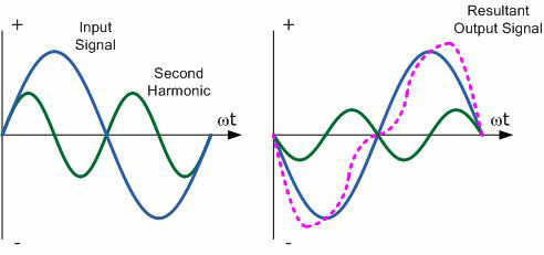
Amplitude Distortion greatly reduces the efficiency of an amplifier circuit. These "flat tops" of the distorted output waveform either due to incorrect biasing or over driving the input do not contribute anything to the strength of the output signal at the desired frequency. Having said all that, some well known guitarist and rock bands actually prefer that their distinctive sound is highly distorted or "overdriven" by heavily clipping the output waveform to both the +ve and -ve power supply rails. Also, excessive amounts of clipping can also produce an output which resembles a "square wave" shape which can then be used in electronic or digital circuits. We have seen that with a DC signal the level of gain of the amplifier can vary with signal amplitude, but as well as Amplitude Distortion, other types of distortion can occur with AC signals in amplifier circuits, such as Frequency Distortion and Phase Distortion. Frequency Distortion Frequency Distortion occurs in a transistor amplifier when the level of amplification varies with frequency. Many of the input signals that a practical amplifier will amplify consist of the required signal waveform called the "Fundamental Frequency" plus a number of different frequencies called "Harmonics" superimposed onto it. Normally, the amplitude of these harmonics are a fraction of the fundamental amplitude and therefore have very little or no effect on the output waveform. However, the output waveform can become distorted if these harmonic frequencies increase in amplitude with regards to the fundamental frequency. For example, consider the waveform below: Frequency Distortion due to Harmonics
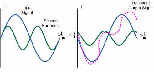
In the example above, the input waveform consists a the fundamental frequency plus a second harmonic signal. The resultant output waveform is shown on the right hand side. The frequency distortion occurs when the fundamental frequency combines with the second harmonic to distort the output signal. Harmonics are therefore multiples of the fundamental frequency and in our simple example a second harmonic was used. Therefore, the frequency of the harmonic is 2 times the fundamental, 2 x f or 2f. Then a third harmonic would be 3f, a fourth, 4f, and so on. Frequency distortion due to harmonics is always a possibility in amplifier circuits containing reactive elements such as capacitance or inductance. Phase Distortion Phase Distortion or Delay Distortion occurs in a non-linear transistor amplifier (or Op-Amp) when there is a time delay between the input signal and its appearance at the output. If we call the phase change between the input and the output zero at the fundamental frequency, the resultant phase angle delay will be the difference between the harmonic and the fundamental. This time delay will depend on the construction of the amplifier and will increase progressively with frequency within the bandwidth of the amplifier. For example, consider the waveform below: Phase Distortion due to Delay
Any practical amplifier will have a combination of both "Frequency" and "Phase" distortion together with amplitude distortion but in most applications such as in audio amplifiers or power amplifiers, unless the distortion is excessive or severe it will not generally affect the operation of the system. |

|
|
|
Contact email: qooljaq@qooljaq.com |