 |
|
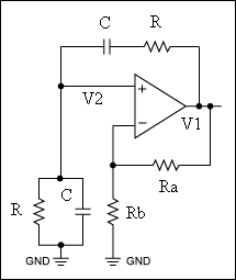
There are three types of RC oscillators, Wien Bridge, Twin-T, and Phase-Shift. The the simplest oscillators is the Wien Bridge Oscillator. Fig 1 shows a typical Wien bridge oscillator. The circuit relies on a series RC network and a parallel RC network causing a phase shift of 0 degrees at one particular frequency at the non inverting input. Thus, taking the signal at the + input, through the op amp, through R and C and back to the + input causes a phase shift of 0 degrees at one particular frequency.
Fig. 1 The feedback resistors Ra and Rb set the gain to maintain oscillation. The Wien bridge oscillator can be understood most readily by first considering the transfer function of the RC network that forms the feedback loop. Calculating V2/V1 we find
For wRC = 1 the signal at the input of the amplifier is exactly in phase with that at the output, and if the amplifier has a gain of at least 3 (to compensate for the factor 1/3 in V2/V1) the circuit will oscillate with a frequency of
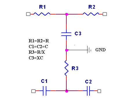
When the gain of the amplifier is slightly larger than 3, the output amplitude will grow until it saturates the amplifier, when the gain is less than 3 it will decay until the oscillator stops. An easy way of analysing this circuit is to consider the gain and phase shift caused by the Wien bridge network (the series and parallel RC components) and ignore the other components in the circuit, as shown in Fig 2. At a specific frequency, the phase shift caused by the series RC is offset by an equal and opposite phase shift caused by the parallel RC, so the net phase shift is zero. When this occurs, the circuit will oscillate. Fig 2 The second common design is called a "Twin-T" oscillator as it uses two "T" RC circuits operated in parallel. One circuit is an R-C-R "T" which acts as a low-pass filter. The second circuit is a C-R-C "T" which operates as a high-pass filter. Together, these circuits form a bridge which is tuned at the desired frequency of oscillation. The signal in the C-R-C branch of Twin-T filter is advanced, in the R-C-R - delayed, so they may cancel one another for frequency of if X = 2; if it is connected as a negative feedback to an amplifier, and X>2, the amplified becomes an oscillator.
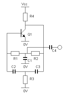
Fig 3 The Twin-T is a band-stop RC circuit (or notch filter). It blocks all but the resonant frequency
Oscillation cannot occur at frequencies above or below the resonant frequency. Twin-T Audio Oscillator
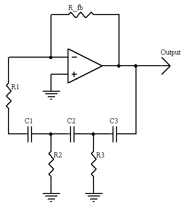
Fig 4 R1 = R2 Vcc is not critical, 6 to 12Vshould work fine. Higher or lower voltages may also work. Another common design is the Phase-shift oscillators. One of the simplest implementations for this type of oscillator uses an operational amplifier (op-amp), three capacitors and four resistors, as shown in Fig 5.
Fig 5 The filter must be designed so that at frequencies above and below the oscillation frequency the signal is shifted by either more or less than 180 degrees. This results in constructive superposition for signals at the oscillation frequencies, and destructive superposition for all other frequencies. The calculations are greatly simplified by setting all the resistors (except the negative feedback resistor) and all the capacitors to the same values. In the diagram, if R1 = R2 = R3 = R, and C1 = C2 = C3 = C, then:
Where: and the oscillation criterion is: |
|
|
|
Contact email: qooljaq@qooljaq.com |


