 |
|
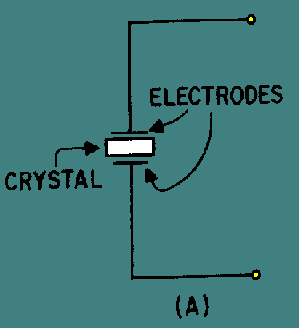
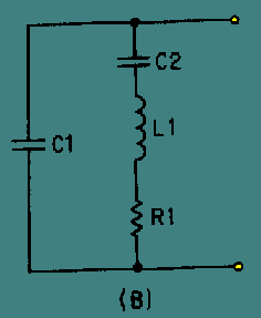
Crystal-controlled oscillators produces a output which is highly stable and at a very precise frequency. The amount of current that can safely pass through a crystal ranges from 50 to 200 milliamperes. When the rated current is exceeded, the amplitude of mechanical vibration becomes too great, and the crystal may crack. Overloading the crystal affects the frequency of vibration because the power dissipation and crystal temperature increase with the amount of load current. A quartz crystal and its equivalent circuit are shown in figure 1 and 2. Capacitor C2, inductor L1, and resistor R1 in Fig. 2 represent the electrical equivalent of the quartz crystal in Fig. 1. Capacitance C1 represents the capacitance between the crystal electrodes in Fig. 1. Depending upon the circuit characteristics, the crystal can act as a capacitor, an inductor, a series-tuned circuit, or a parallel-tuned circuit.
Fig 1
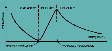
Fig 2 At some frequency, the reactances of equivalent capacitor C2 and inductor L1 will be equal and the crystal will act as a SERIES-TUNED circuit. It has a MINIMUM impedance at this series resonance frequency (see figure 3). Above this frequency the crystal acts as an INDUCTOR, and below this frequency it acts as a CAPACITOR. The impedance increases as the frequency is lowered because the crystal unit acts as a capacitor. The impedance of the crystal unit also increases as the frequency is raised above the series-resonance point because the unit acts as an inductor. Therefore, the crystal unit can be used as a SERIES-RESONANT crystal.in an oscillator circuit.
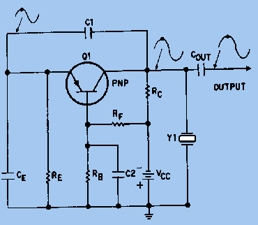
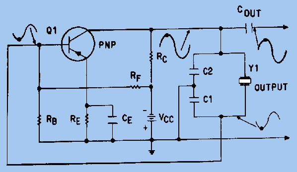
Fig 3 Since the crystal unit acts as an inductor above the series resonance point, it becomes equivalent to an inductor that is parallel with the equivalent capacitor C1 (Fig 2). At some frequency above the series resonance point, the reactances of equivalent capacitor C1 and inductor L1 will be equal and the crystal unit will act as a PARALLEL-TUNED circuit. It has a MAXIMUM impedance at this parallel resonance frequency and acts as an INDUCTOR below this frequency (see figure 3). Therefore, the crystal unit can also be used as a PARALLEL-RESONANT crystal.in an oscillator circuit. Resonance modes A quartz crystal provides both series and parallel resonance frequency. The series resonance is a few kilohertz lower than the parallel one. There is no such thing as a “series cut” crystal as opposed to a “parallel cut” crystal. The same crystal can be made to oscillate in series resonance mode or parallel resonance mode. The frequency of oscillation of a crystal is usually specified by the manufacturer as either the series resonance frequency or the parallel resonance frequency. A crystal can oscillate in series resonance, meaning that L1 is resonating with C2 (Fig 2). Some oscillator circuits are designed for series resonance and the oscillation frequency shall equal the specified series resonance value. These series mode oscillators, however, are more sensitive to temperature and component variations. In fact, most crystals oscillators in today's ICs are of the parallel resonance type. The oscillation frequency of a parallel mode oscillator is always higher than a series mode oscillator. The actual oscillation frequency of a parallel mode oscillator is dependent on the equivalent capacitance seen by the crystal. At parallel resonance, the crystal behaves inductively and resonates with capacitance shunting the crystal terminals. Depending on the application, especially in microprocessors where Pierce oscillators are used predominantly, a crystal manufacturer may specify parallel resonance frequency instead of series resonance frequency. Crystals below 30 MHz are generally operated between series and parallel resonance, which means that the crystal appears as an INDUCTIVE reactance in operation. Adding additional capacitance across a crystal will cause the parallel resonance to shift downward. This can be used to adjust the frequency at which a crystal oscillator operates. Crystals above 30 MHz (up to >200 MHz) are generally operated at series resonance where the impedance appears at its minimum and equal to the series resistance. To reach higher frequencies, a crystal can be made to vibrate at one of its overtone modes, which occur at multiples of the fundamental resonant frequency. Only odd numbered overtones are used. Such a crystal is referred to as a 3rd, 5th, or even 7th overtone crystal. To accomplish this, the oscillator circuit usually includes additional LC circuits to select the wanted overtone. LC circuits are used either for generating signals at a particular frequency, or picking out a signal at a particular frequency from a more complex signal (such as a Crystal Oscillator). Q Factor In physics and engineering the quality factor or Q factor is a dimensionless parameter that describes how under-damped an oscillator or resonator is, or equivalently, characterizes a resonator's bandwidth relative to its center frequency. Higher Q indicates a lower rate of energy loss relative to the stored energy of the oscillator; the oscillations die out more slowly. A pendulum suspended from a high-quality bearing, oscillating in air, has a high Q, while a pendulum immersed in oil has a low one. Oscillators with high quality factors have low damping so that they ring longer. Sinusoidally driven resonators having higher Q factors resonate with greater amplitudes (at the resonant frequency) but have a smaller range of frequencies around that frequency for which they resonate; the range of frequencies for which the oscillator resonates is called the bandwidth. Thus, a high Q tuned circuit in a radio receiver would be more difficult to tune, but would have more selectivity; it would do a better job of filtering out signals from other stations that lay nearby on the spectrum. High Q oscillators oscillate with a smaller range of frequencies and are more stable. The quality factor of oscillators vary substantially from system to system. Systems for which damping is important (such as dampers keeping a door from slamming shut) have Q = 1/2. Clocks, lasers, and other resonating systems that need either strong resonance or high frequency stability need high quality factors. Tuning forks have quality factors around Q = 1000. The quality factor of atomic clocks and some high-Q lasers can reach as high as 10e+11 and higher. A major reason for the wide use of crystal oscillators is their high Q factor. The Q of a crystal is many times greater than that of an LC tank circuit. The high Q is present because the resistance in the crystal is extremely small. Commercially produced crystals range in Q from 5,000 to 30,000. The high Q causes the frequency stability to be much greater than that of an ordinary LC tank circuit. This is the reason a crystal is used in many sine-wave generator circuits. A typical Q value for a quartz oscillator ranges from 104 to 106, compared to perhaps 102 for an LC oscillator. The maximum Q for a high stability quartz oscillator can be estimated as Q = 1.6 × 10⁷/f, where f is the resonance frequency in megahertz. One of the most important traits of quartz crystal oscillators is that they can exhibit very low phase noise. In many oscillators, any spectral energy at the resonant frequency will be amplified by the oscillator, resulting in a collection of tones at different phases. In a crystal oscillator, the crystal mostly vibrates in one axis, therefore only one phase is dominant. This property of low phase noise makes them particularly useful in telecommunications where stable signals are needed, and in scientific equipment where very precise time references are needed. Environmental changes of temperature, humidity, pressure, and vibration can change the resonant frequency of a quartz crystal, but there are several designs that reduce these environmental effects. These include the TCXO, MCXO, and OCXO (defined below). These designs often produce devices with excellent short-term stability. The limitations in short-term stability are due mainly to noise from electronic components in the oscillator circuits. Long term stability is limited by aging of the crystal. Due to aging and environmental factors (such as temperature and vibration), it is difficult to keep even the best quartz oscillators within one part in 10e?10 of their nominal frequency without constant adjustment. For this reason, atomic oscillators are used for applications requiring better long-term stability and accuracy. Although crystals can be fabricated for any desired resonant frequency, within technological limits, in actual practice today engineers design crystal oscillator circuits around relatively few standard frequencies, such as 3.58 MHz, 10 MHz, 14.318 MHz, 20 MHz, 33.33 MHz, and 40 MHz. The vast popularity of the 3.58 MHz and 14.318 MHz crystals is attributed initially to low cost resulting from economies of scale resulting from the popularity of television and the fact that this frequency is involved in synchronizing to the color burst signal necessary to display color on an NTSC or PAL based television set. Using frequency dividers, frequency multipliers and phase locked loop circuits, it is practical to derive a wide range of frequencies from one reference frequency. Crystal-Controlled Pierce Oscillator The crystal-controlled PIERCE OSCILLATOR uses a crystal unit as a parallel-resonant circuit. The Pierce oscillator is a modified Colpitts oscillator. They operate in the same way except that the crystal unit replaces the parallel-resonant circuit of the Colpitts. Figure 4 shows the common-base configuration of the Pierce oscillator. Feedback is supplied from the collector to the emitter through capacitor C1. Resistors RB, RC, and RF provide the proper bias conditions for the circuit and resistor RE is the emitter resistor. Capacitors C1 and CE form a voltage divider connected across the output. Since no phase shift occurs in the common-base circuit, capacitor C1 feeds back a portion of the output signal to the emitter without a phase shift. The oscillating frequency is determined not only by the crystal but also by the parallel capacitance caused by capacitors C1 and CE. This parallel capacitance affects the oscillator frequency by lowering it. Any change in capacitance of either C1 or CE changes the frequency of the oscillator. Figure 4 - Pierce oscillator, common-base configuration.
Fig 4 Figure 5 shows the common-emitter configuration of the Pierce oscillator. The resistors in the circuit provide the proper bias and stabilization conditions. The crystal unit and capacitors C1 and C2 determine the output frequency of the oscillator. The signal developed at the junction between Y1 and C1 is 180 degrees out of phase with the signal at the junction between Y1 and C2. Therefore, the signal at the Y1-C1 junction can be coupled back to the base of Q1 as a regenerative feedback signal to sustain oscillations. Figure 5. - Pierce oscillator, common-emitter configuration.
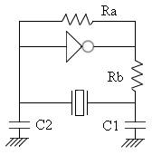
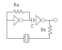
Fig 5 Series vs. Parallel "Series" resonant crystals are intended for use in circuits which contain no reactive components in the oscillator feedback loop. "Parallel" resonant crystals are intended for use in circuits which contain reactive components (usually capacitors) in the oscillator feedback loop. Such circuits depend on the combination of the reactive components and the crystal to accomplish the phase shift necessary to start and maintain oscillation at the specified frequency. Basic depictions of two such circuits are shown below.
Fig 6 The Figure above shows implementation of a parallel resonant oscillator circuit.
Fig 7 The Figure above shows implementation of a series resonant oscillator circuit. |
|
|
|
Contact email: qooljaq@qooljaq.com |
